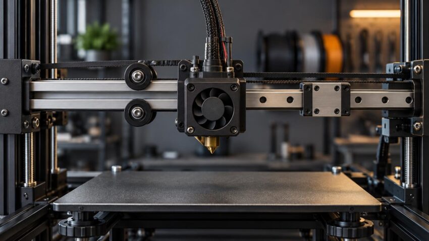
TLDR: In the linear rails vs v wheels 3d printer decision, neither guide system guarantees better prints. Properly adjusted V-wheels can work well on a light FDM machine, while linear rails can support a compact, rigid motion system when the printer is designed or carefully converted around them. Before buying parts, inspect the existing guides, belts, pulleys, frame and toolhead. Convert only when you can identify a mechanical limitation and install the rails on accurate, suitably stiff mounts.
The most useful way to approach linear rails vs v wheels 3d printer hardware is as a system-design question, not a ranking of two components. Wheel preload, rail alignment, mounting accuracy, contamination and maintenance can matter more than the guide format itself. A well-installed rail may be a sensible engineering choice; a poorly aligned conversion can introduce binding, distortion and a longer troubleshooting chain.
What is mechanically different?
A V-wheel carriage uses rollers that run against angled surfaces on an extrusion. Many consumer printers use polymer wheels and an eccentric spacer or nut to move one wheel closer to the extrusion. That adjustment removes lateral play, but it also creates the risk of excessive preload. The target is a carriage that does not rock yet still travels smoothly without unnecessary resistance.
Manufacturer maintenance guidance for these systems commonly calls for checking wheel tightness, cleaning debris from the running surfaces and replacing worn wheels when needed. Adjustment should remove lateral movement without making the carriage difficult to move; excessive tightening can accelerate wear.
A profiled linear guide instead consists of a hardened rail and a carriage containing rolling elements. Those elements circulate through the carriage as it moves, constraining motion along the rail. This packages guidance into a compact assembly, but it does not remove the need for an accurate mounting surface, correct alignment, contamination control or lubrication. THK’s overview of profiled LM guides explains the underlying rail-and-carriage arrangement.
The practical distinction is therefore not “precise rail” versus “imprecise wheel.” It is a difference in how loads are carried, how the guide is mounted and how faults are adjusted or repaired.
| Decision factor | V-wheels on extrusion | Profiled linear rails |
|---|---|---|
| Routine adjustment | Eccentric adjustment can remove play, but excessive preload adds drag and wear | No wheel eccentric to tune, but mounting alignment and carriage condition remain critical |
| Running surfaces | Exposed extrusion and wheel surfaces are easy to inspect and clean | Rail raceways and carriage require protection from debris and suitable lubrication |
| Wear response | Individual wheels can be inspected and replaced | Service depends on the rail, carriage and supplier instructions |
| Mounting sensitivity | Depends on straight extrusion, sound wheels and correct preload | Depends strongly on mounting-surface accuracy, rigidity and rail alignment |
| Conversion effort | Existing system may need only cleaning, adjustment or replacement wheels | Often requires mounts, fasteners, alignment work and checks for changed geometry |
| Best reason to choose it | The existing light-duty system already moves smoothly and holds adjustment | The machine was designed for rails or a verified conversion solves a defined constraint |
Do linear rails improve print quality?
Not automatically. Print quality is the result of the complete machine: frame stiffness, belts, pulleys, motors, drive settings, toolhead rigidity, extrusion consistency, bed support, slicing and motion tuning all contribute. Changing the guide hardware while leaving the actual fault untouched may produce no visible improvement.
Rails also cannot compensate for an inaccurate conversion mount. Linear-guide manufacturers warn that mounting rigidity and accuracy affect guide loading and operation. A rail forced to follow a warped or poorly aligned surface may bind or load its carriage unevenly. THK’s handling precautions for LM guides cover mounting accuracy, contamination and lubrication requirements.
Nor does installing rails make a printer faster by itself. Higher acceleration depends on a suitable combination of moving mass, frame stiffness, motor capability, belt path, control settings and vibration behavior. A rail can be one component of a motion system designed for demanding movement, but it is not a substitute for designing and tuning that system.
Inspect V-wheels before replacing them
If a wheel-guided printer once produced acceptable results and has gradually developed play, rough travel or inconsistent positioning, maintenance is the logical first step. It is cheaper, faster and more diagnostic than changing the guide architecture.
- Power down the printer and follow its manufacturer’s safety guidance before moving or servicing an axis.
- Inspect the extrusion tracks and wheel surfaces for dust, fragments or other debris. Clean them using methods approved for the printer and wheel material.
- Hold the carriage and check for rocking perpendicular to its intended direction of travel. Movement here can indicate insufficient wheel contact, loose hardware or another mechanical fault.
- Move the carriage through its full range. Look for a local tight spot, repeated bump, roughness or excessive resistance rather than judging only one position.
- Inspect the wheels for visible damage, irregular wear or deformation. Replace worn parts with compatible components rather than attempting to compensate indefinitely with more eccentric preload.
- Adjust the eccentric only enough to remove lateral play while retaining smooth movement. Recheck the full travel after tightening nearby fasteners.
- Inspect belt tension, pulley security, frame fasteners and toolhead mounting before running a calibration print.
A wheel that can be turned with no connection to carriage movement may be too loose, but the opposite extreme is not desirable. Crushing the wheel against the extrusion can increase resistance and wear. The useful test is whether the assembled carriage remains stable and moves smoothly, following the printer maker’s adjustment procedure where one is available.
What motion-guide faults can look like
Loose or damaged guide components may contribute to carriage rocking, rough travel, position-dependent resistance or inconsistent mechanical support. Binding can also make an axis harder to move in one area than another. These observations justify closer inspection, but they do not identify the guide as the sole cause of a printed artifact.
Ringing, inconsistent layers and dimensional variation can also arise from loose belts, insecure pulleys, frame movement, toolhead play, aggressive acceleration or extrusion variation. First-layer trouble additionally points toward bed condition, leveling, gantry geometry and Z-offset. Repeating Z artifacts may involve lead screws, couplers, gantry alignment or contamination. Diagnose the printer physically before buying a motion conversion.
A useful isolation process
- With power safely removed, check the suspected carriage for play and rough travel.
- Inspect fasteners, belts, pulleys and attached assemblies on the same axis.
- Note whether resistance occurs everywhere or at a repeatable position.
- Correct one confirmed fault at a time, then repeat the same test print and settings.
- If the artifact remains, continue through extrusion, frame, bed and tuning variables rather than assuming the new guide hardware must be defective.
When a linear-rail conversion makes sense
A conversion is easiest to justify when it addresses a defined mechanical requirement. Examples include a carriage design that cannot reliably retain wheel adjustment, a custom toolhead that needs a different mounting arrangement, or a larger redesign in which rail geometry is integral to the structure. It can also make sense as part of a documented printer build whose mounts, carriage positions and alignment process were designed together.
Treat a conversion as a small machine-building project rather than a bolt-on quality setting. That means checking drawings, tolerances, fastener access, belt alignment, endstop operation and usable travel before ordering. Owners considering a broader rebuild may find the same project-selection principles in our guide to evaluating open-source printer projects.
Verify these points before buying a kit or collecting parts:
- The exact printer revision and extrusion dimensions supported by the conversion
- Rail length, carriage type, carriage count and fastener pattern
- Whether the rail position changes nozzle reach, build volume or belt geometry
- Mount stiffness and the flatness or straightness expected from the mounting surface
- Clearance for the bed, enclosure, wiring, drag chains, endstops and toolhead
- A documented alignment and tightening sequence
- A maintenance plan based on the printer and rail supplier’s instructions
- A realistic path back to the original configuration if the conversion does not solve the problem
Compatibility labels alone are not enough. Printers sold under the same product name can have revision changes, and a bracket that physically fits may still reposition a belt or carriage. Prefer a conversion with dimensioned documentation and evidence that its designer considered the whole axis.
Why rail installation quality matters
A profiled rail should not be used to pull a badly shaped mounting surface into submission. The mounting structure must provide suitable support, and the rail must be aligned without forcing the carriage through tight spots. Mounting rigidity and accuracy affect the loads within a linear guide, while debris and unsuitable lubrication can interfere with its operation.
Before final tightening, verify that the carriage moves consistently over the intended travel using the conversion designer’s procedure. If two rails constrain one assembly, their relationship becomes especially important: each guide may move acceptably alone yet bind when connected through a rigid gantry.
Do not apply a universal cleaning fluid, grease or oil recommendation. Rail suppliers can specify different products, while printer manufacturers may establish their own service method. THK gives approximately 100 kilometres of travel or three to six months as a general lubrication starting point for its LM Guides, but explicitly makes the interval dependent on operating conditions. Prusa’s XL maintenance instructions provide a printer-specific example of checking rails for debris and lubricating them at three-to-six-month intervals using specified materials. That schedule is relevant to the XL, not a universal rule for every conversion. Prusa’s XL maintenance guidance
Enclosures and larger printers require a system view
Rails are often discussed in connection with enclosed or larger machines, but enclosure heat does not make mounting geometry irrelevant. A steel rail attached to an aluminium extrusion combines materials with different thermal expansion behavior. As temperatures change, the assembly can bend slightly or shift stress between its components. Voron’s tuning documentation specifically notes this behavior in rail-and-extrusion assemblies.
That does not mean rails are unsuitable for heated printers. It means the frame, rail location, fastener strategy and operating temperature must be considered together. A machine engineered around rails can account for these interactions; an improvised conversion may not.
A keep, repair or convert decision path
Keep the V-wheels when the carriage is stable, travel is smooth and the printer meets its intended workload. There is little value in replacing a functioning guide system simply because rails appear more industrial.
Service or replace the wheels when cleaning and correct adjustment resolve the problem, or when inspection reveals worn consumable parts. This preserves the machine’s original geometry and gives you a clearer diagnosis.
Consider converting when a repeatable guide-related limitation remains after the rest of the axis has been checked, and when a well-documented design addresses that limitation. The conversion should provide known fitment, suitable mounting stiffness, a credible alignment procedure and maintainable replacement parts.
Common questions about rails and wheels
Are linear rails always more accurate than V-wheels?
No universal print-level advantage can be assumed. Rail quality, mount accuracy, alignment and carriage condition matter, while V-wheel results depend on wheel condition, extrusion geometry and preload. Either arrangement can underperform when installed or maintained poorly.
Can a rail conversion perform worse than the original wheels?
Yes. A misaligned rail, inaccurate bracket, weak mount or altered belt path can introduce binding or unwanted movement. The relevant comparison is between complete, correctly assembled axes—not isolated components.
How tight should V-wheels be?
Tight enough to remove lateral carriage play, but not so tight that movement becomes resistant or rough. Check the printer manufacturer’s procedure because eccentric layouts and adjustment methods vary.
Why does a newly installed linear rail bind?
Possible causes include mounting-surface error, rail misalignment, contamination, an incompatible or distorted bracket, uneven tightening, or misalignment between multiple guides. Stop and isolate the mechanical cause rather than forcing the carriage or attempting to hide resistance with stronger motors.
What should I check before blaming the motion guides?
Check carriage play, belts, pulley fasteners, frame joints, toolhead mounting, bed support, lead screws where applicable and whether resistance changes with axis position. Also confirm that the observed defect is not coming from extrusion or motion settings.
The practical takeaway
Start with evidence from the machine in front of you. Clean and inspect its guides, remove play without adding drag, and rule out belts, pulleys, mounts and frame faults. If properly serviced V-wheels move smoothly and hold the carriage securely, keeping them is a sound decision.
Choose linear rails when they are part of a coherent design or solve a demonstrated mechanical constraint. Verify fitment, mounting quality, alignment and maintenance before buying. The guide type matters, but the quality of the complete motion system determines whether the change is an upgrade.
References
- The linear guide rail systems on 3D printer axes: All you need to know – Snapmaker
- Linear Guides & Accessories
- THK | LM Guide Application
- Handling Precautions|LM Guide®|Product Information|THK Official Web Site [Japan/English]
- Regular printer maintenance (XL) | Prusa Knowledge Base
- Secondary Printer Tuning | Voron Documentation