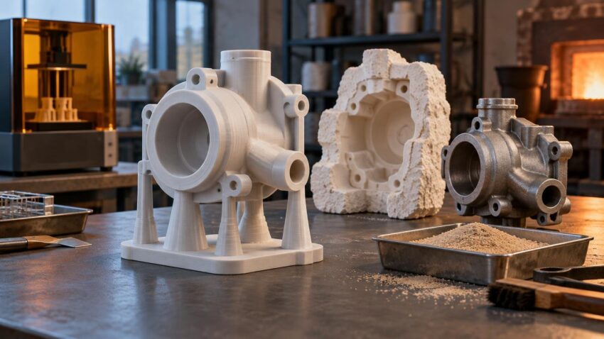
TLDR: 3d printed casting patterns replace the conventional pattern-making step, not necessarily the mold itself. For investment casting, the print is normally sacrificed during dewaxing or burnout. For conventional sand casting, a durable printed pattern may be withdrawn and reused. Directly binder-jetting a sand mold or core is a third, patternless route. Choose among them by working backward from the foundry’s mold system, burnout capability, required finish, part size, quantity, and tolerance plan.
The attraction of 3d printed casting patterns is straightforward: a foundry can move from CAD data to a casting trial without first machining dedicated pattern tooling. That can shorten iteration cycles for prototypes, replacement parts, complex one-offs, and bridge production. The print, however, becomes part of a larger casting process. A dimensionally accurate pattern can still fail if it expands during burnout, leaves residue, admits slurry into a hollow interior, or carries layer texture into the metal part.
The practical answer is to treat additive manufacturing as one controlled stage in a hybrid workflow. Select the pattern process with the foundry, design around molding and burnout requirements, finish only the surfaces that matter, and qualify the complete pattern-to-casting route before committing valuable alloy or production capacity.
What is a 3D-printed casting pattern?
A 3D-printed casting pattern is a physical replica used to create the cavity into which molten metal will eventually flow. Its role depends on the casting process.
- A sacrificial investment-casting pattern is enclosed in investment material or coated repeatedly to build a ceramic shell. The pattern is then removed by dewaxing, thermal burnout, or a process combining both steps.
- A reusable sand-casting pattern is pressed or molded into foundry sand and withdrawn before pouring. It must therefore incorporate suitable draft, parting features, and allowances for the selected molding process.
- A directly printed sand mold or core is not a printed pattern. Binder jetting forms the mold components from digital data, eliminating the conventional pattern-making and molding steps.
This distinction matters when requesting quotes. Asking for a “3D-printed mold” when the project actually needs a sacrificial pattern can lead to discussion of the wrong equipment, material, tolerances, and cost structure.
Where the pattern fits in investment casting
A typical digital investment-casting route begins with the casting model rather than an unmodified end-use CAD file. The model must account for the foundry’s expected process contraction, machining stock, distortion strategy, and any geometry needed for assembly or handling. The pattern is then printed, cleaned, finished, inspected, and attached to a gating system.
- Prepare the casting model with foundry-approved allowances.
- Choose the pattern material and printing process around the shell or investment system.
- Orient, print, clean, and post-process the pattern.
- Inspect critical dimensions and seal any openings that could admit slurry.
- Attach the pattern to the sprue and gating assembly.
- Build the investment mold or ceramic shell.
- Remove the pattern with the validated dewaxing and burnout cycle.
- Fire or condition the mold, pour the alloy, and allow it to solidify.
- Remove the shell, cut off gates, finish the casting, and inspect the result.
The sequence resembles lost-wax casting, but a printed polymer does not necessarily behave like foundry wax. Softening temperature, thermal expansion, decomposition, ash, wall thickness, and trapped material all influence whether the pattern exits cleanly without damaging the mold.
Five practical pattern routes
| Route | Typical role | Main advantage | Main control point |
|---|---|---|---|
| Direct wax printing | Sacrificial investment-casting pattern | Wax-like foundry workflow and fine detail | Printer access, handling, support removal, and pattern cost |
| Castable photopolymer resin | Sacrificial investment or ceramic-shell pattern | High detail from accessible resin platforms | Complete post-cure, burnout behavior, residue, and shell compatibility |
| PMMA printing | Sacrificial investment-casting pattern | Useful route for larger or demanding industrial patterns | Thermal removal strategy, geometry, and foundry validation |
| FDM filament pattern | Sacrificial pattern or low-cost master | Low equipment cost and practical access to larger build volumes | Layer texture, seams, hollow construction, expansion, and burnout |
| Reusable printed pattern | Conventional sand molding | Avoids machining a wood, polymer, or metal pattern for short runs | Draft, wear, rigidity, release, parting strategy, and dimensional stability |
Direct wax printing
Direct wax systems produce sacrificial patterns rather than masters from which another wax pattern must be made. This can be attractive where fine features, smooth surfaces, and compatibility with an established wax-oriented workflow matter more than the lowest printer cost.
For example, 3D Systems describes its ProJet MJP 2500 IC as a system for 100% wax casting patterns, with a published build volume of 294 × 211 × 144 mm and stated output of up to 205 cm³ per hour. The company positions it for low- to mid-volume and bridge-manufacturing applications. Those figures describe that specific machine rather than direct-wax printing as a whole.
Castable photopolymer resin
Castable resin can reproduce small text, thin features, and detailed surfaces, but “castable” should not be interpreted as universally compatible. Post-curing, pattern mass, support placement, investment chemistry, airflow, furnace capability, and the burnout schedule all affect the outcome.
Formlabs states that its Castable Wax Resin contains 20% wax and reports thermogravimetric-analysis ash content of 0.0–0.1%. It also notes that results vary with factors including geometry, orientation, print settings, and temperature. These are useful product-specific inputs, but the foundry still needs to validate the complete process.
PMMA patterns
PMMA is another sacrificial-pattern option used in industrial investment casting. It can suit geometries or production environments where the selected printing system and foundry process have already been developed around the material. ExOne documents the use of binder-jetted PMMA patterns in an aerospace investment-casting case study, illustrating that the route extends beyond jewelry-scale work.
FDM and burnout filament
FDM makes pattern printing accessible and can accommodate parts larger than many resin or wax systems. The tradeoff is that visible layers, extrusion seams, support scars, and imperfectly sealed shells can become casting defects or increase finishing labor.
Ordinary PLA is sometimes used in lost-pattern experiments, while specialty filaments are formulated for more favorable burnout behavior. Neither label guarantees success. In a peer-reviewed 2026 comparison conducted with a particular ceramic-shell setup, PolyCast patterns produced less ceramic-mold damage after burnout than PLA patterns under the tested conditions. That result supports process-specific material selection, not a universal ranking for every shell, geometry, and furnace cycle. Readers evaluating this route can consult the published PLA and PolyCast pattern study.
Reusable printed sand-casting patterns
A printed pattern can also replace a machined pattern used to form a conventional sand mold. Because it must be withdrawn rather than burned out, the design normally needs draft, a workable parting line, adequate stiffness, and surfaces that release cleanly. Wear and dimensional stability become increasingly important as the number of molds rises.
For a successful short run, a printed polymer pattern may be sufficient. For repeated molding, the print may instead serve as a master for more durable tooling. This is the same broad bridge-tooling logic used around other manufacturing processes: prove the geometry and workflow before investing in longer-life tooling. See 3D printing for fixtures and bridge tooling for the wider production context.
Design controls that determine casting quality
Start with the foundry’s dimensional model
Do not apply a generic percentage to every axis and call the pattern finished. The required compensation can include alloy solidification contraction, mold behavior, process history, machining stock, and anticipated distortion. Ask the foundry to approve the casting model and identify which dimensions are controlled in the printed pattern, after casting, or through machining.
Treat layer lines as transferred geometry
Investment material reproduces the pattern surface. Pronounced print layers, support contact marks, sanding flats, filler edges, and uncured resin can therefore affect the casting. Orient the pattern so support scars and stair-stepping avoid sealing faces, bearing locations, visible cosmetic surfaces, and thin edges.
Finishing should be selective. Sanding every surface can consume the time saved by printing and can alter dimensions. A better plan identifies critical surfaces in CAD, uses orientation to protect them, and measures them after finishing.
Design hollow patterns cautiously
Hollow or lattice-filled patterns reduce material, but they introduce new failure modes. Slurry can enter through an opening or porous wall, become trapped, and create internal ceramic that obstructs pattern removal. Enclosed structures can also change how heat and gases move through the pattern.
Investment Casting Institute technical material specifically addresses forces on additive-manufactured patterns during autoclave dewax and cautions associated with hollow or quasi-hollow construction. The implication is practical: wall thickness, drainage, sealing, venting, and removal method must be planned together rather than optimized independently.
Develop gating with the foundry
A printable shape is not automatically a castable shape. Sprues, runners, gates, vents, and feeders influence mold filling, solidification, and casting yield. Their design depends on the alloy and casting process, so they should not be improvised merely because additive manufacturing can produce complex branches.
Why burnout validation is essential
Ceramic-shell cracking can occur when a polymer pattern expands or generates pressure faster than the surrounding shell can tolerate. Residue can contaminate the cavity, while an incomplete cycle may leave obstructions or a poor surface. Large solid sections and trapped internal structures can make removal more difficult than a thin, vented geometry made from the same material.
A responsible qualification trial uses representative wall thicknesses, enclosed features, surface finishes, gates, and maximum section sizes. A small decorative test coupon does not qualify a much larger industrial pattern. Record the complete combination of printer settings, material batch, cleaning and curing steps, pattern age, shell system, drying conditions, furnace loading, temperature cycle, and observed results.
Where castings require formal production approval, pattern printing should be included in the controlled process rather than treated as an informal model-making step. The broader principles of traceability, process qualification, inspection, and release authority are covered in our guide to additive-manufacturing certification and standards.
When direct-printed sand is the better route
If the intended process is sand casting, directly printing the sand mold and cores may remove the need for a physical pattern altogether. Binder jetting can create mold components and complex internal cores from CAD data, including geometries that would be difficult to withdraw from conventionally rammed sand. ExOne describes this as a patternless route for producing sand molds and cores.
Direct-printed sand deserves consideration when internal passages drive the design, pattern withdrawal would impose unwanted draft or parting constraints, or a one-off casting does not justify separate pattern tooling. A reusable printed pattern may remain preferable when a foundry already has an efficient molding line, the geometry releases cleanly, and several similar molds are required.
The decision is therefore not “print or do not print.” It is where printing removes the most expensive or restrictive step: the sacrificial pattern, the reusable pattern, the master used to make pattern tooling, or the sand mold and core package.
How to choose a workflow
- Ask the foundry which printed pattern materials and removal cycles it already supports.
- Decide whether the project needs a sacrificial pattern, a reusable pattern, a tooling master, or directly printed sand.
- Define required finish, critical dimensions, machining stock, and inspection points before selecting a printer.
- Compare the complete route, including printing, cleaning, curing, sealing, finishing, gating, shell building, burnout, casting yield, and rework.
- Run a representative qualification casting rather than relying only on a material datasheet or a small generic coupon.
- Freeze the validated printer settings, material, post-processing, shell system, and thermal cycle for repeat work.
- Reassess dedicated tooling if quantities rise or pattern finishing becomes the production bottleneck.
Printed patterns usually make the strongest case for one-offs, prototypes, replacement components, design iterations, and bridge production because they avoid an initial tooling commitment. That does not establish a universal economic break-even point. At higher quantities, a printed master used to create wax-injection tooling—or conventional durable tooling made after the design stabilizes—may reduce labor and variation per pattern.
Conclusion
The best route for 3d printed casting patterns starts with the foundry process, not the printer. Direct wax and castable resin emphasize detail; PMMA offers an established industrial pattern route in selected workflows; FDM provides accessibility and build-size flexibility; reusable printed patterns support conventional sand molding; and binder-jetted sand can eliminate the pattern entirely.
Before printing a production pattern, send the foundry the CAD model, material proposal, wall construction, intended post-processing, and required quantity. Ask for its approved allowances and burnout or molding requirements. That early review is the simplest way to prevent a good print from becoming an expensive casting failure.
References
- ProJet MJP 2500 IC – 3D Printer | 3D Systems
- Castable Wax Resin | Formlabs
- 3D-printed PMMA patterns for aerospace casting – exone
- Assessing the Use of 3D Printed Patterns for Use in Investment Casting | International Journal of Metalcasting | Springer Nature Link
- TCE 2024 Presentations_Tuesday – INVESTMENT CASTING INSTITUTE
- www.investmentcasting.org
- 3D Printed Sand Casting Molds & Cores | ExOne