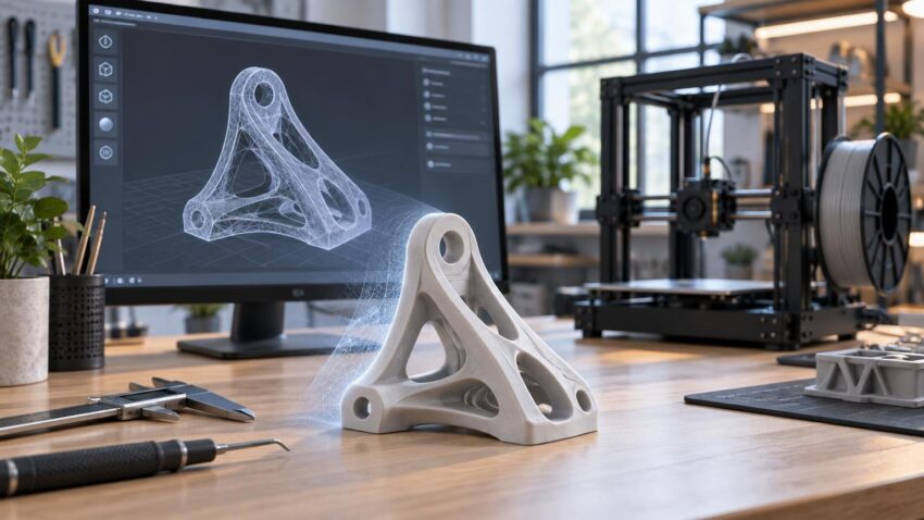
TLDR: AI 3D modeling for 3D printing can shorten the journey from an idea or reference image to editable geometry. It is particularly useful for decorative objects, miniatures, terrain, props, and concept models. It does not automatically produce a watertight, dimensionally accurate, mechanically sound, or support-free part. Treat the generated model as a starting point: inspect the mesh, repair defects, rebuild critical features, establish scale, slice it, and make a test print.
The practical breakthrough in AI 3D modeling for 3D printing is not push-button manufacturing. It is faster creation of plausible first-pass geometry. A prompt that once required hours of sculpting may now produce a rough mesh in minutes, while a reference image can provide shape, color, and proportion cues. The difficult handoff comes afterward, when visually convincing geometry must become a physical object that a particular printer and material can reproduce.
That distinction matters because a rendered asset only needs to look correct from the camera. A printable object needs coherent surfaces, sufficient wall thickness, suitable clearances, a deliberate scale, a stable orientation, and features that survive the chosen process. AI accelerates ideation; mesh tools, CAD, slicers, and physical testing still determine whether the result works.
What text-to-3D and image-to-3D actually produce
Text-to-3D systems interpret a written description and generate geometry that resembles it. Prompts can specify the subject, broad style, major shapes, symmetry, pose, and details to avoid. Some systems also offer separated parts: Tripo’s documentation, for example, describes a generate_parts option intended to create individual elements as editable parts. That can be useful when a base, figure, accessory, or articulated component needs separate processing.
Image-to-3D starts with visual evidence rather than text alone. Meshy and Tripo document workflows built around uploaded images, while Tripo recommends a clearly visible subject with limited occlusion. A clean three-quarter view, uncluttered background, even lighting, and visible silhouette generally give a generator more useful information than a dark, cropped, or heavily obstructed photograph.
Neither method can recover information that the input does not contain with certainty. A single photograph does not reveal the back of an object, internal cavities, true dimensions, or the way two hidden surfaces connect. The system must infer those details. The result may be plausible, but plausible is not the same as measured. Multiple views can reduce ambiguity, yet critical dimensions should still be established in CAD or against measured references.
| Tool category | Best role in the workflow | What still needs attention |
|---|---|---|
| Text-to-3D generation | Rapid concepts, stylized forms and prompt-driven variations | Topology, scale, thin features and unseen geometry |
| Image-to-3D generation | Reconstructing the apparent form of a visible subject | Hidden surfaces, proportions, input rights and dimensional accuracy |
| AI-assisted mesh processing | Remeshing, segmentation and faster cleanup operations | Loss of detail, changed dimensions and unresolved defects |
| DCC and mesh-repair software | Sculpting, retopology, manifold checks and local repairs | Mechanical constraints and exact interfaces |
| Parametric CAD | Measured holes, mating faces, clips, lids and assemblies | Organic detail and the effort required to rebuild geometry |
| Slicer software | Orientation, supports, toolpaths and print previews | Printer, material and profile limitations |
Where AI-generated geometry is most useful
AI-generated meshes fit best when visual character matters more than exact engineering intent. Decorative sculptures, creature miniatures, tabletop terrain, cosplay ornaments, prop shells, reliefs, planters, and early industrial-design concepts are natural candidates. These objects still require preparation, but their organic surfaces are usually easier to repair or resculpt than to recreate from scratch in parametric CAD.
Prompting should reflect the intended manufacturing workflow. For a miniature, request a stable pose, clearly separated limbs, substantial weapons or accessories, and no floating details. For terrain, specify a flat base, accessible cavities, broad structural connections, and restrained surface noise. For a hollow prop, ask for a simple exterior shell but expect to create the actual wall thickness, splits, alignment pins, and joining surfaces later.
AI is less appropriate as the sole design method for exact-fit replacement parts, brackets, gears, bearing seats, threaded components, snap fits, lids, enclosures, or load-bearing assemblies. Such parts depend on dimensions, tolerances, material behavior, and design intent that a visually generated mesh does not inherently contain. A model shaped like a clip is not necessarily a functional clip.
For these applications, use AI for concept exploration or the aesthetic shell, then rebuild the interfaces in parametric CAD. A practical hybrid enclosure might combine an organic AI-generated outer surface with measured mounting bosses, connector openings, screw holes, clearance zones, and mating faces created as controlled CAD features.
A reliable AI 3D modeling for 3D printing workflow
- Generate several candidates rather than committing to the first result. Choose the model with the clearest silhouette, simplest topology, strongest symmetry, and fewest fused or floating details.
- Import the selected mesh into a capable mesh editor. Inspect it in solid, wireframe, and face-orientation views instead of judging only the shaded render.
- Remove unwanted fragments and repair structural defects. Address open boundaries, internal surfaces, self-intersections, disconnected islands, degenerate faces, and inconsistent normals.
- Edit the geometry for production. Thicken fragile details, flatten the intended contact area, separate parts where helpful, and simplify details that will fall below the printer’s useful feature size.
- Move dimension-critical features into CAD. Establish measured interfaces, clearances, holes, pins, threads, and mating surfaces with explicit dimensions rather than visual estimates.
- Set units and final scale. AI-generated assets may arrive without a meaningful real-world size, so verify dimensions before export and again after import into the slicer.
- Choose an exchange format supported by the next application, then slice with the actual printer, nozzle or exposure settings, layer height, and material profile.
- Inspect the complete toolpath preview. Look for missing walls, unsupported islands, unexpectedly solid cavities, tiny isolated extrusions, weak first-layer contact, and excessive support.
- Print a reduced-risk prototype. For mechanical parts, test the interface or critical section before committing to a long full-scale build. Revise the source model rather than relying on slicer compensation for every problem.
The mesh-cleanup checks that matter
A printable mesh should describe an unambiguous solid. In plain terms, the software must be able to determine what is inside the object and what is outside. A manifold mesh normally has a continuous closed skin, with edges participating in a consistent surface instead of ending unexpectedly or joining an impossible number of faces.
Blender’s 3D Print Toolbox provides checks for non-manifold geometry, intersecting faces, thin areas, sharp-edge thinning, and overhangs, as well as a Make Manifold cleanup operation. Blender’s 3D Print Toolbox documentation explains the available checks. Automated repair is useful, but the repaired result still needs visual inspection: closing a hole in the mathematically simplest way can create the wrong shape.
- Open or non-manifold edges: Find gaps, branching surfaces, and places where the skin does not define a closed volume.
- Face normals: Make sure surfaces consistently face outward. Reversed regions can be interpreted as holes or produce confusing repairs.
- Self-intersections and internal faces: Remove surfaces that pass through one another or remain trapped inside the final shell unless they serve a deliberate purpose.
- Disconnected islands: Delete accidental fragments, or separate intentional components into independently printable objects.
- Degenerate and highly distorted geometry: Collapse duplicate vertices and repair zero-area or needle-like faces that can destabilize later operations.
- Wall thickness and minimum features: Compare thin walls, spikes, embossed details, and gaps with the chosen process, material, nozzle, layer height, or resin exposure setup.
- Overhangs and bridges: Decide whether to change the geometry, rotate the part, split it, or add supports. A watertight model can still be impractical to manufacture.
- Base contact and orientation: Give the part a stable build strategy rather than assuming its visually upright pose is also its best printing orientation.
Manufacturability cannot be reduced to a single universal mesh test. NIST describes design-for-additive-manufacturing rules as relationships between design features and process or material parameters; support requirements for overhangs in material extrusion are one process-specific example. NIST’s work on additive-manufacturing manufacturability analysis reinforces why printer and process constraints must be considered alongside geometry.
Mesh editing versus parametric CAD
Mesh editing works directly with vertices, edges, and faces. It is the natural environment for smoothing a creature, closing a hole, sculpting folds, reducing polygon count, separating shells, or changing an organic silhouette. It is less convenient when a hole must remain exactly positioned and sized after several revisions.
Parametric CAD represents dimensions, sketches, constraints, and feature relationships. It is the stronger choice when changing one measurement should predictably update other geometry. A mounting plate with a defined hole pattern, an enclosure with controlled wall thickness, or a lid with a designed clearance belongs in this environment even if an AI mesh inspired its overall appearance.
Conversion between the two representations can be awkward. Dense triangle meshes may overwhelm CAD tools or arrive as thousands of unrelated faces rather than editable features. Instead of trying to convert every polygon into a parametric object, simplify the mesh and use it as a visual reference. Rebuild only the surfaces and interfaces that need engineering control.
Why a good render can fail in the slicer
Rendering software can hide or visually smooth many geometric problems. A surface may look continuous even when it contains overlapping shells, tiny gaps, inverted faces, or details with no printable thickness. Textures can also create the appearance of scales, seams, or panel lines that are not present in the geometry at all.
The slicer asks different questions. Does the model enclose a volume? Is a wall thick enough to receive a toolpath? Where does each new layer obtain support? Can separated regions start in mid-air? Is the contact area stable? The layer preview, rather than the attractive source render, is the decisive digital inspection stage.
Do not assume a vendor’s remesh, repair, high-resolution, or export option constitutes print approval. Meshy documents optional remeshing, geometry-resolution controls, and output-format choices in its image-to-3D workflow, but those settings address asset generation and processing rather than validating a particular physical build.
STL or 3MF for an AI-generated model?
STL remains a common denominator for moving triangle geometry between modeling software and slicers. Its simplicity is useful, but an STL does not inherently provide the richer package of manufacturing information that newer formats can carry. Units can also become an import assumption, which is why scale should always be checked.
The 3MF Consortium presents 3MF as a format intended to transfer fuller-fidelity 3D models among applications, platforms, services, and printers. Its Core Specification includes requirements for model and solid-support meshes, including manifold edges and consistently outward-oriented surfaces. The specification suite was recognized as ISO/IEC 25422:2025, according to the consortium’s specification index and July 31, 2025 announcement.
Use 3MF when the applications at both ends support the information you need and preserve it correctly. Use STL when compatibility is the overriding concern or only the surface mesh needs to move. Neither format repairs bad geometry merely by containing it: exporting a broken mesh as 3MF does not make it manifold, and converting it to STL does not establish the right scale or wall thickness.
Licensing, ownership, and cloud confidentiality
Before uploading an image, scan, CAD file, or product reference, confirm that you have the right to use it and review the service’s current terms. Provider rules may differ on commercial use, ownership, generated output, training use, retention, and private processing. A paid plan should not be assumed to grant every right required for resale or client work.
Cloud confidentiality deserves separate consideration. Do not upload unreleased products, customer CAD, protected characters, sensitive scans, or proprietary manufacturing data unless the service’s current terms and your own agreements permit it. For commercial work, record the tool, plan, terms date, inputs, major edits, and output version so the design history can be reconstructed.
The practical takeaway
Use AI when the main obstacle is creating or exploring shape. Use mesh software when the shape exists but its surface needs repair or artistic revision. Use parametric CAD when dimensions, fits, constraints, or repeatable changes control success. Use the slicer to test the manufacturing plan, and use a physical prototype to validate what software cannot guarantee.
That sequence keeps AI in its most productive role: an acceleration layer rather than an automatic approval system. For decorative work, it can remove much of the blank-page effort. For functional work, it can supply inspiration or an outer form, but the engineered interfaces still need deliberate design and validation. A successful print is not simply generated; it is generated, repaired, designed, sliced, and tested. The same distinction becomes even more important when moving from a prototype to an approved additive-manufacturing production part.
References
- Text to model (H3) | Tripo OpenAPI docs
- Image to 3D API | Meshy Docs
- Image to 3D Model — Tripo Developers
- 3D Print Toolbox — Blender Manual
- A DESIGN FOR ADDITIVE MANUFACTURING ONTOLOGY TO SUPPORT MANUFACTURABILITY ANALYSIS | NIST
- Specification – 3MF Consortium
- 3mf.io
- 3MF: An ISO Standard for the Future of Additive Manufacturing – 3MF Consortium