TLDR
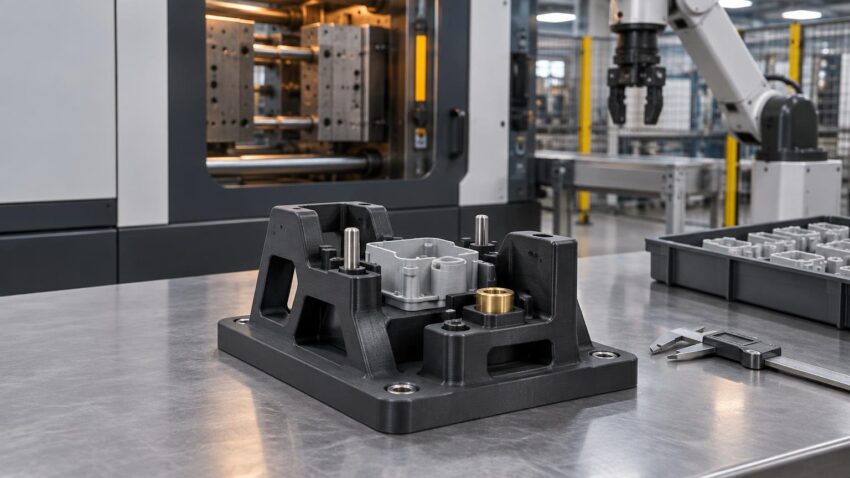
3d printing injection molding fixtures makes the most sense for production aids used around the molding process: insert-loading guides, part nests, inspection fixtures, secondary-operation tooling, dunnage, gauges, and robot end effectors. These applications can exploit fast CAD iteration and geometry tailored to the part without placing an ordinary printed polymer tool inside the mold. A fixture should not be confused with a printed mold or mold insert, which faces a fundamentally different combination of heat, pressure, wear, and process risk.
The practical question is not whether 3d printing injection molding fixtures is possible. It is whether a particular tool can locate, support, protect, or move a molded component repeatedly under its actual operating conditions. Start with low-risk production aids, design from functional datums, add metal or replaceable interfaces where wear occurs, and validate the printed tool before releasing it to the molding floor.
Where 3D printing injection molding fixtures fits best
Injection molding involves much more than the mold itself. Inserts may need to be oriented before a cycle, hot parts may need to be presented to an operator or robot, molded components may require trimming or labeling, and finished parts may need dimensional inspection. Those surrounding tasks are often better candidates for printed tooling than the molding cavity is.
Manufacturer documentation describes additive manufacturing being used for holding and alignment tools, inspection fixtures, gauges, dunnage, end effectors, and other jigs and fixtures. These examples demonstrate the range of possible production aids, although they do not establish universal life, load, accuracy, or temperature limits for every printed tool.
| Application | What the printed tool does | Main design concern |
|---|---|---|
| Insert loading | Orients and presents metal inserts before molding | Reliable orientation, clearance, and operator access |
| Part handling | Supports or presents molded parts after ejection | Part temperature, warp, cosmetic contact, and grip security |
| Inspection fixture | Locates a part for CMM, probe, camera, or manual inspection | Datum strategy, stability, access, and fixture repeatability |
| Secondary operation | Holds a part for trimming, drilling, assembly, labeling, or marking | Cutting loads, debris, surface protection, and tool clearance |
| Go/no-go gauge | Provides a quick attribute check for a selected feature | Gauge wear, calibration strategy, and measurement uncertainty |
| Dunnage and kitting | Separates, protects, and presents parts or inserts | Impact, contamination, cleanability, and mistake-proofing |
| Robot end effector | Carries fingers, nests, vacuum routing, or sensor mounts | Payload, acceleration, fatigue, fasteners, and fail-safe behavior |
A useful first project is usually a fixture whose failure would stop a task or produce an obvious loading error rather than damage a mold, injure an operator, or release a defective part undetected. That gives the team room to learn how its printer, material, orientation, and post-processing choices affect fit and durability.
Fixture, jig, printed mold, or bridge tooling?
The terms are sometimes used loosely, but their functions differ. A fixture primarily locates and holds a workpiece. A jig also guides a tool or operation, such as positioning a drill. Either can be printed as a manufacturing aid.
A 3D-printed injection mold or mold insert is different because it forms the molded component and is exposed directly to the injection-molding process. NIST identifies additive manufacturing as applicable to molds, mold inserts, and patterns for processes including injection molding, confirming that these are legitimate additive-manufacturing applications. They nevertheless belong to a separate tooling problem from a part nest or inspection fixture. Readers can review the broader process scope in the NIST overview of additive manufacturing.
Bridge tooling generally means an interim tool used to produce parts while production tooling is unavailable, under development, or uneconomic for the required volume. It may include printed tooling in a suitable process, but “bridge” does not mean lightly engineered. Tool material, cavity design, cooling, molding resin, machine settings, expected cycles, dimensional requirements, and failure consequences all affect whether a printed mold solution is viable.
A simple boundary keeps project scope clear: if the printed component touches molten material, defines the molded surface, sits in the mold stack, or carries mold-clamping and injection-related loads, treat it as mold tooling. Do not qualify it using the lighter assumptions appropriate to a bench fixture.
High-value applications around the molding cell
Insert loading and verification
An insert-loading aid can arrange threaded inserts, contacts, bushings, or other components in the correct orientation before they enter the mold. Pockets, asymmetric profiles, color contrast, labels, and blocked incorrect orientations can provide poka-yoke, or mistake-proofing. The design must still allow realistic manufacturing variation and easy removal; a nominally exact CAD pocket can become a frustrating press fit after printer variation, insert tolerances, or contamination are considered.
Inspection nests and checking fixtures
A printed nest can support a complex molded surface while leaving measured features accessible. Stratasys presents an injection molder, Thogus Products, as a customer example involving a printed coordinate measuring machine fixture. It is a useful illustration of the application, not a universal benchmark for achievable accuracy or service life.
An inspection fixture should locate the component from the same functional relationships that matter on the drawing or in assembly. Avoid forcing a warped or flexible molding into an idealized CAD shape, because the fixture may hide the condition being measured. Use the minimum practical locating scheme, provide relief around nonfunctional surfaces, and allow probes or optical systems an unobstructed path.
Secondary operations and finishing
Printed supports can hold molded parts for gate trimming, drilling, assembly, marking, pad printing, labeling, or decal application. A conformal surface can distribute contact over a larger area than a few hard points, but the printed texture and trapped debris may mark cosmetic parts. A Stratasys guide describes a conformal, non-marring FDM fixture for decal or label application at Mercury Marine. That example concerns a finishing operation, not direct exposure to injection pressure or molten polymer.
Dunnage, presentation, and robot tooling
Custom trays and dunnage can keep components separated, establish orientation, and present parts consistently to operators, cameras, or robots. End-of-arm tooling can also benefit from printed geometry that integrates air routing, sensor brackets, cable management, or part-specific fingers. Low mass may help an automation application, but the complete load case includes acceleration, emergency stops, off-center moments, hose forces, fastener pullout, and fatigue—not just the static weight of the part.
Choosing a printing process without relying on a material label
Process selection should begin with the fixture’s environment and failure mode. A familiar material name alone does not establish suitability because printed properties depend on the process, formulation, orientation, geometry, build parameters, conditioning, and post-processing.
- Material-extrusion processes such as FDM are practical candidates for many robust general-purpose aids, particularly when large geometry, internal structure, or easy iteration matters. Layer orientation, heat exposure, and fastener interfaces require deliberate design.
- Powder-bed polymer processes can produce complex, support-free geometry and nested features. Surface texture, dimensional behavior, moisture or chemical exposure, and cleaning requirements still need evaluation.
- Vat photopolymerization can suit detailed features, smooth contact geometry, or compact gauges when the selected resin and post-cure are appropriate. Brittleness, creep, aging, chemical contact, and temperature exposure must be checked for the actual formulation.
- Metal additive manufacturing may be justified when the complete fixture needs metal properties or geometry that is difficult to machine, but it is not the automatic answer to every wear point.
- A hybrid fixture often provides the most controlled solution: a printed body combined with metal pins, bushings, threaded inserts, rails, wear pads, heat shields, or a machined base.
The goal is not to maximize the percentage of the tool that is printed. It is to place each material where it contributes useful geometry, compliance, wear resistance, thermal behavior, or repeatability.
Design rules that matter on the production floor
Additive manufacturing permits complex geometry, but a production fixture still has to obey workholding fundamentals. ISO/ASTM 52900 provides common additive-manufacturing vocabulary, while ISO/ASTM 52910 gives general design guidance for additive manufacturing. These standards provide a useful framework, but they do not replace application-specific fixture qualification. ISO/ASTM 52900 information from ASTM
- Locate from functional datums. Use surfaces, holes, edges, or bosses that establish the relationships the operation needs to control.
- Do not overconstrain the part. Moldings can shrink, warp, or vary by cavity and process condition. Too many rigid contact points can cause rocking, forced seating, or false inspection results.
- Provide loading clearance. Include lead-ins, chamfers, finger access, ejector features, and room for gloves where appropriate.
- Separate location from clamping. Locators establish position; clamps keep the part seated. Asking flexible printed walls to perform both jobs can reduce consistency.
- Use replaceable contact elements. Wear pads, soft contact strips, vacuum cups, pins, and bushings can be replaced without discarding the entire body.
- Reinforce mechanical interfaces. Use suitable inserts, through-bolts, backing plates, or captured hardware where repeated tightening or pullout loads would challenge printed threads.
- Protect appearance surfaces. Move hard contacts to hidden or robust areas, remove sharp edges, control debris, and validate that texture or residue will not transfer.
- Design for inspection and cleaning. Provide access to critical regions and avoid crevices that retain chips, oil, release agents, dust, or fragments.
- Make orientation obvious. Asymmetric geometry, keyed loading, clear identification, and visible status features can reduce operator errors.
- Control the digital definition. Record the model revision, build orientation, material, printer or process, key parameters, post-processing, and any installed hardware.
Designing for additive manufacturing is not merely removing material or replacing a machined block with a printed copy. The fixture should exploit conformal support, integrated features, accessible cavities, and easy revision while preserving stable interfaces where precision and wear matter.
When metal or a hybrid fixture is the better choice
Choose metal, or add metal interfaces, when the fixture faces sustained heat, concentrated clamping loads, abrasive sliding, impact, tight bearing fits, frequent fastener service, or a metrology requirement that the selected printed process cannot maintain. Metal is also the safer default when an undetected fixture change could release nonconforming product or when failure could create a significant operator or machine hazard.
This does not require an all-metal design. A machined base can establish the coordinate system while a printed nest supports the changing part geometry. Hardened dowel pins can locate the component, a metal bushing can guide a cutter, or replaceable polymer pads can protect a cosmetic surface. Hybrid construction makes the precision and wear elements serviceable while retaining the speed and geometric freedom of a printed body.
A release and validation checklist
A fixture is not production-ready simply because it fits one part after printing. Validation should reflect the operation, expected variation, and consequences of failure. The following sequence is a practical starting point, not a universal qualification standard.
- Inspect the finished fixture. Check critical geometry, flatness, contact surfaces, hardware installation, defects, and any post-processing that could affect fit.
- Test representative molded parts. Include expected variation where possible, such as parts from different cavities, process conditions, lots, or cooling states.
- Verify the locating strategy. Confirm that the part seats consistently without being forced and that operators can detect incomplete or incorrect loading.
- Exercise the real load case. Test clamping, tool reaction, robotic acceleration, part removal, repeated handling, and credible misuse appropriate to the application.
- Evaluate the environment. Consider part temperature, ambient heat, oils, cleaners, mold-release agents, coolants, humidity, ultraviolet exposure, and cleaning methods.
- Check product protection. Look for scratches, gloss changes, transferred residue, dents, contamination, or distortion at all contacts.
- Confirm measurement capability. For inspection tooling, include the fixture in the measurement-system review and monitor wear or movement that could bias results.
- Review ergonomics and safety. Examine pinch points, sharp edges, lifting, reach, visibility, stored energy, and what happens if the fixture breaks or a part is loaded incorrectly.
- Run repeated cycles. Inspect for cracks, creep, loosened hardware, worn locators, dimensional drift, and accumulating debris at an interval justified by the risk.
- Release a controlled revision. Identify the fixture, approved build specification, acceptance checks, maintenance interval, replacement criteria, and responsible release authority.
Production release should sit within the manufacturer’s quality system. The broader distinction between a printed object and an approved production item is explored in additive-manufacturing certification and qualification, including process control, testing, and release authority.
Common questions
Can 3D-printed fixtures be used in injection molding?
Yes. They can support insert loading, inspection, handling, assembly, finishing, dunnage, and automation around an injection-molding operation. Suitability depends on the actual loads, temperature, chemicals, accuracy requirement, cycle demands, and failure consequences.
How should a fixture accommodate shrinkage and warp?
Locate the part from functional datums, add clearance to noncritical surfaces, and avoid forcing flexible geometry into nominal CAD form. Test parts representing realistic cavity and process variation. For inspection, make sure the nest reveals rather than conceals the deformation being evaluated.
Can a printed fixture support CMM inspection?
It can, provided the fixture is sufficiently stable and its uncertainty is understood for the measurement task. Probe access, datum simulation, thermal behavior, seating consistency, wear, and verification of the completed fixture all matter. A printed CMM nest is not automatically a calibrated gauge.
When are pins, bushings, or threaded inserts useful?
Use them where repeated contact, accurate location, guided motion, or routine fastener service would wear or damage the printed material. They are also useful when an interface must be replaceable or independently inspected.
Can the same design rules be used for a printed injection mold?
No. Printed molds and mold inserts require separate engineering for molding pressure, thermal cycling, heat transfer, cavity finish, venting, ejection, molding-material compatibility, machine settings, and safe failure behavior. A successful handling fixture does not demonstrate that the same material or process is suitable inside a mold.
Start with a bounded production problem
The strongest case for 3D-printed tooling around injection molding is not a blanket replacement of machined fixtures. It is the ability to solve a clearly bounded production problem with geometry tailored to the part and operation. An insert-loading guide, conformal inspection nest, protected labeling support, or lightweight handling tool can be an effective first application.
Select a task with observable failure, document its requirements, and decide which interfaces need metal or replaceable elements. Then validate fit, cycling, environment, ergonomics, and process control before release. That approach preserves the speed and design freedom of additive manufacturing without confusing a convenient printed aid with qualified mold tooling.
References
- FDM Jigs Fixtures and Manufacturing Tools
- 3D Printed Jigs and Fixtures
- How to 3D Print In-House Jigs, Fixtures, and Other Manufacturing Aids | Formlabs
- Additive Manufacturing/3D Printing | NIST
- SOLUTION GUIDE
- ISO/ASTM52900 Additive manufacturing — General principles — Fundamentals and vocabulary
- ISO/ASTM52910 Standard Guidelines for Design for Additive Manufacturing